In the earlier posts we talked about various types of CAN, the contents of a CAN message called the Frame, some basics on reading and writing data using NI's two popular APIs, and we talked about other non-NI APIs. In this post we're going to talk about ways of embedding data into the CAN frame payload, and ways to scale that information to engineering units. This is the basis for what is called a Signal.
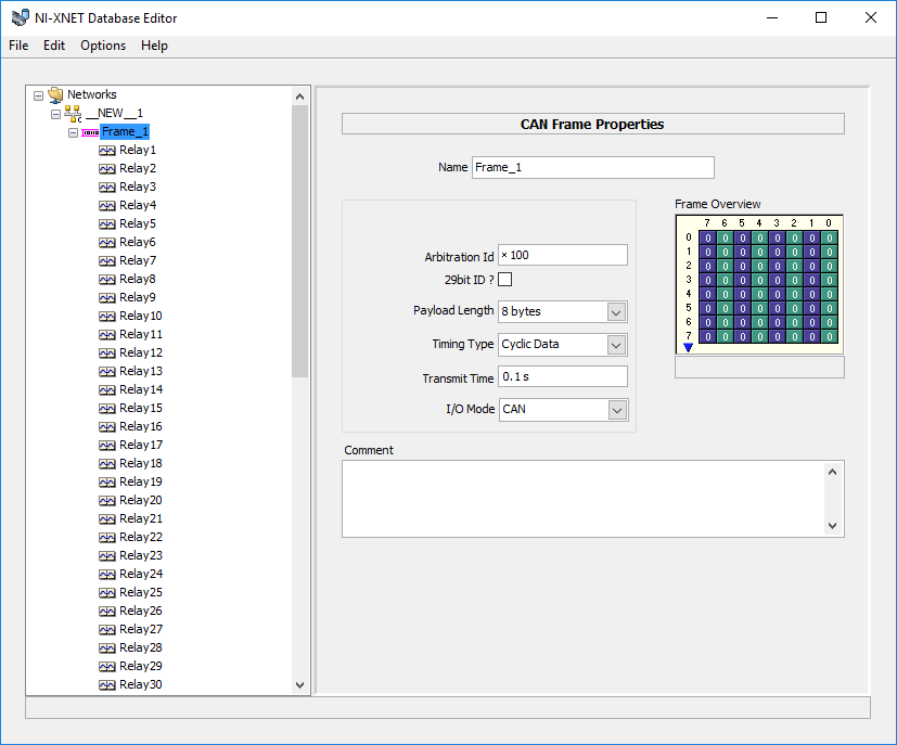
Here we see a frame named "Frame_1". It has an ID of 0x100, it is not extended, it has 8 bytes of payload, is a Cyclic Data type (meaning it is expected to be sent periodically) and at a rate of 0.1s. We also see the Frame Overview which shows a representation of the 8 bytes (vertically) and each of the 8 bits in each byte (horizontally). The purple and green represent the bits in the payload that are being taken up by the Signals. We have 64 Signals named "Relay1", through "Relay64".

If we select a Signal we see more details about it, like the Start Bit, Number of Bits, Minimum, Maximum, Default Value, Unit, Scale Factor, Offset, Byte Order, Data Type, and a few other parameters. A nice visualization also shows us what bits are being used by this signal, which in this case isn't very interesting. Remember that Signals all go out (or come in) just as a Frame, and that Signals are just ways to embed data into the Frame. We could send a Frame with ID 0x100, and 8 bytes of payload and it will be sent just the same. But by having an abstraction layer we can address a Signal by name, not by ID, start bit, bit length, and scaling information.
Lets imagine for a second we listen to our car's CAN bus, and we see a Frame with ID 0x200 and the following four bytes as the payload 0x12 34 56 78. What does this mean? Well if we have the database defined, or get the definition from some other location, we might have be able to see this.

We can see with the database that the first two bytes are the RPM and the next two are the Engine_Temp. We can take the RPM bytes of 0x12 34 and apply the scale of 0.4 and get an RPM of 5332.0. We can then take the next two bytes of 0x56 78 and scale the Engine_Temp to be 54.03. Without this information trying to figure out what bytes mean what can be very difficult. If we are simulating a car then the act of using Signals makes writing them easier too. Instead of trying to perform calculations to figure out what the raw bytes should be, we can just write the values as engineering units.
But even when writing information it is much easier to write a Signal, and have the database scale it to a Frame then it is to have static code converting a number into a frame.
In LabVIEW there is a limitation on the number of bits in a signal. Because signals are read and written as the double data type, they are limited to 52. This means if you have a signal that is more than 52 bits, the only way to read or write it is using the Frame API where the payload is sent as an array of bytes.


Using the XNet Database we can convert from frames, to signals, and back from signals, to frames. Here is an example but we will go over this in more detail when we talk more about the XNet API.

The thing to note about this is that no scale information is hard coded. It is all contained in the database, which can be imported from a DBC file. This means if a DBC is updated to have different scaling, or range, the software doesn't need to be updated if it is written in a way that imports the database. When written well this can make for very flexible software, since the database can be selected by the user of the software, or easily updated in the future.
Using the XNet API for conversion I found several undesired features, and potential bugs. So I re-wrote the conversion functions into native G code and posted it here. (as a side effect it is a bit faster than the XNet code too) This includes a couple of examples and a DBC to see how conversion using a file and raw frames, can be done. The conversion tools are part of the Hooovahh CAN Frame Signal Conversion package, or on the downloads page for this blog series.

64 Bits, 64 Signals
So in Part 2 when we talked about the CAN frame I talked about the payload of a CAN frame, and how in almost all situations this is between 0 and 8 bytes of data, in 1 byte increments. I also gave a few short examples on what can be in this 8 bytes of data. The example involved wanting to send the status of 64 relays, which can either be open or close. I could assign a 0 as Open and a 1 as Close, and then take up each of the 64 bits, and assign it to one of the 64 relays. In this way I make 64 Signals, which all get sent (or received) with that one frame using one ID. The XNet Database Editor is a very useful tool for visualizing and editing basic CAN databases so here is an example of a single CAN frame, containing 64 Signals, each being assigned a name.Here we see a frame named "Frame_1". It has an ID of 0x100, it is not extended, it has 8 bytes of payload, is a Cyclic Data type (meaning it is expected to be sent periodically) and at a rate of 0.1s. We also see the Frame Overview which shows a representation of the 8 bytes (vertically) and each of the 8 bits in each byte (horizontally). The purple and green represent the bits in the payload that are being taken up by the Signals. We have 64 Signals named "Relay1", through "Relay64".
If we select a Signal we see more details about it, like the Start Bit, Number of Bits, Minimum, Maximum, Default Value, Unit, Scale Factor, Offset, Byte Order, Data Type, and a few other parameters. A nice visualization also shows us what bits are being used by this signal, which in this case isn't very interesting. Remember that Signals all go out (or come in) just as a Frame, and that Signals are just ways to embed data into the Frame. We could send a Frame with ID 0x100, and 8 bytes of payload and it will be sent just the same. But by having an abstraction layer we can address a Signal by name, not by ID, start bit, bit length, and scaling information.
Lets imagine for a second we listen to our car's CAN bus, and we see a Frame with ID 0x200 and the following four bytes as the payload 0x12 34 56 78. What does this mean? Well if we have the database defined, or get the definition from some other location, we might have be able to see this.
We can see with the database that the first two bytes are the RPM and the next two are the Engine_Temp. We can take the RPM bytes of 0x12 34 and apply the scale of 0.4 and get an RPM of 5332.0. We can then take the next two bytes of 0x56 78 and scale the Engine_Temp to be 54.03. Without this information trying to figure out what bytes mean what can be very difficult. If we are simulating a car then the act of using Signals makes writing them easier too. Instead of trying to perform calculations to figure out what the raw bytes should be, we can just write the values as engineering units.
But even when writing information it is much easier to write a Signal, and have the database scale it to a Frame then it is to have static code converting a number into a frame.
In LabVIEW there is a limitation on the number of bits in a signal. Because signals are read and written as the double data type, they are limited to 52. This means if you have a signal that is more than 52 bits, the only way to read or write it is using the Frame API where the payload is sent as an array of bytes.
Muxed Signals
I won't go into too much detail on this subject just because I don't see it used that often. But one way to pack more information into a single CAN ID is to multiplex a signal. Lets say I want to transmit the voltage of some circuit and I want to transmit its current. If I've ran out of room in my 8 bytes of payload, one option instead of using up another CAN ID might be to multiplex the signal. I can designate the first bit to be a 0 or a 1, and maybe if it is 0 then the rest of the data in the frame corresponds to current, and if it is a 1 the signal corresponds to voltage. For visualization lets again look at the XNet Database Editor.
So in this case the first bit is for a signal called the Designator. If this signal is a 0 then the next 7 bits are for Current, but if it is 1 then the next 7 bits are for Voltage. They can both have their own separate scaling, offset, units, and others settings associated with a signal. Of coarse this means you can't read both voltage and current at the same time, since they share the same ID and will have to be read one after the other but for some signals like temperature which aren't expected to change often, this might be a better design.
The DBC File
The industry standard format for containing the information that allows turning Signals into Frames, and Frames into Signals, is the .DBC file or CAN Database which is a mostly human readable text file. This DBC can be imported into an XNet database, and an XNet database can be exported into a DBC. Use the LabVIEW Import or Export function on Windows targets to use DBC files programatically, or use the XNet Database Editor to import, edit and export manually. When using other external tools like CANalyzer, this DBC file is crucial in understanding the data being read, and easily sending the data back. There are multiple tools for parsing, and editing DBC files. I tend to use a combination of the XNet Database Editor, and CANDB++ made by Vector which is a free tool usually included with other Vector software.Using the XNet Database we can convert from frames, to signals, and back from signals, to frames. Here is an example but we will go over this in more detail when we talk more about the XNet API.
The thing to note about this is that no scale information is hard coded. It is all contained in the database, which can be imported from a DBC file. This means if a DBC is updated to have different scaling, or range, the software doesn't need to be updated if it is written in a way that imports the database. When written well this can make for very flexible software, since the database can be selected by the user of the software, or easily updated in the future.
Signal Frame Conversion
I mentioned earlier that the XNet API allows for reading and writing signals using XNet hardware. But the XNet API also allows for using the conversion tools without requiring hardware. This will take functionality normally ran on the XNet hardware, and gets implemented as software. This is obviously less efficient but when I'm not using XNet hardware it is nice to have another option for database parsing and conversion.Using the XNet API for conversion I found several undesired features, and potential bugs. So I re-wrote the conversion functions into native G code and posted it here. (as a side effect it is a bit faster than the XNet code too) This includes a couple of examples and a DBC to see how conversion using a file and raw frames, can be done. The conversion tools are part of the Hooovahh CAN Frame Signal Conversion package, or on the downloads page for this blog series.

The purpose of this API is to allow for signal and frame conversion on hardware that doesn't support it natively like XNet. All that is needed is the ability to read and write raw frames and all of the APIs featured so far can do that. So now you can write an application where given a DBC a list of signals are shown to read and write from. Then if the hardware (Vector, Intrepid, Kvaser, NI-CAN, NI-XNet) reads frames you can put it through the conversion library and get the signals in engineering units. Then when writing needs to take place you can turn that into the raw frames and write those using the API for that hardware type.